

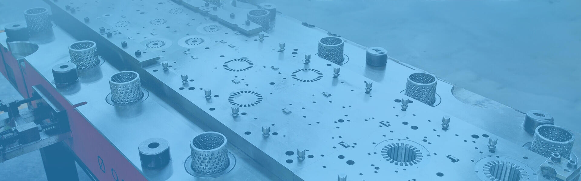
A motor core is the primary magnetic component inside an electric motor responsible for guiding magnetic flux, reducing core losses, and maximizing energy efficiency. Typically constructed from stacked layers of ultra-thin silicon steel laminations, its machining precision, material selection, and stacking technology directly dictate motor efficiency, output torque, thermal dissipation, and operational lifespan. This guide explores motor core structures, key functions, industrial applications, engineering selection criteria, and supplier evaluation benchmarks to help engineers and procurement teams make informed technical decisions.
Key Takeaways
- Core Function: Concentrates magnetic flux and minimizes magnetic leakage as the central magnetic circuit carrier.
- Core Loss Reduction: Suppresses high-frequency eddy current heat through thin electrical steel laminations and inter-sheet insulation.
- Efficiency Determinant: Directly dictates power density, torque output, operating temperature, and energy efficiency ratings (IE3 to IE5).
- Selection Factors: Requires balancing silicon steel sheet thickness, core loss metrics, burr height control, stacking technology (Interlocking vs. Backlack), and dimensional tolerances.
- Quality Benchmark: Stamping burrs and geometric tolerances must be controlled at the micron level (μm) to preserve insulation integrity and air gap uniformity.
1. What is an Electric Motor Core?
An electric motor core is the central magnetic housing within an electric motor engineered to conduct magnetic flux and enable efficient electromagnetic conversion. It is constructed by stacking dozens to hundreds of ultra-thin electrical steel sheets (also known as silicon steel laminations), forming the primary magnetic foundation of the machine.
A complete motor core assembly consists of two main parts:
- Stator Core: The stationary outer assembly featuring perimeter slots to hold copper wire windings, creating a rotating magnetic field when energized. Explore our precision Stator and Rotor Cores for industrial motor applications.
- Rotor Core: The rotating inner component mounted on the drive shaft that reacts to the stator's magnetic field to output rotational mechanical torque.
Why is it the Heart of an Electric Motor?
An electric motor converts electrical energy into magnetic energy, and ultimately into mechanical energy. Copper wire conducts electricity, while the motor core conducts magnetism. Poor magnetic permeability or dimensional inaccuracies lead to flux leakage and excess thermal loss. The quality of a motor core directly determines peak output power, energy efficiency ratings (IE3/IE4/IE5), and overall service life.
2. Key Functions of a Motor Core
A motor core performs several vital electromagnetic and physical functions during operation:
- Guiding Magnetic Flux: Provides a low-reluctance path to concentrate and direct magnetic field lines, maximizing electromagnetic energy utilization.
- Minimizing Core Loss: Reduces hysteresis and eddy current losses through high-permeability materials and insulated coatings.
- Suppressing Eddy Currents: Segmenting the core into insulated laminations restricts eddy current loops, preventing severe thermal losses during high-speed operation.
- Improving Energy Conversion Efficiency: Minimizing heat generation and magnetic leakage allows more input electrical power to convert directly into mechanical output.
- Enhancing Torque Output: Uniform air gaps and optimized slot geometries maintain high dynamic torque even at lower speeds while suppressing cogging torque.
- Reducing Noise and Vibration: Tightly bonded laminations prevent sheet movement caused by alternating magnetic forces, suppressing acoustic hum noise.
- Optimizing Thermal Dissipation: Precision-stacked core assemblies efficiently transfer internal heat from copper windings outward to the frame.
3. Industrial Applications of Motor Cores
Nearly all modern electromagnetic rotating equipment relies on specialized motor cores:
- Electric Vehicles (EV / HEV): Requires high power density and high-speed operation (>15,000 RPM). Uses ultra-thin silicon steel laminations to lower high-frequency core loss and extend driving range.
- Industrial Motors: Used in pumps, fans, and machine tools. Emphasizes continuous operation durability and compliance with IE3/IE4/IE5 efficiency standards.
- Servo Motors: Deployed in CNC machinery and automated production lines. Requires exceptional concentricity and micron-level precision for low torque ripple and precise positioning.
- Semiconductor Equipment: Used in wafer-handling robotics and cleanroom environments where low vibration, low noise, low heat, and high cleanliness are critical.
- Robotics & Joint Actuators: Demands compact sizing and high torque output, utilizing custom thin-profile, multi-pole stator and rotor core designs.
- Variable-Frequency Home Appliances: Found in BLDC compressor motors for air conditioners and washing machines, focusing on cost-efficiency, silent operation, and energy certification.
- Medical Devices: Applied in ventilators and high-speed surgical drills requiring extreme reliability, low temperature rise, and minimal electromagnetic interference (EMI).
4. How to Select a Motor Core: 5 Key Checkpoints
During motor design, prototyping, or mass production sourcing, engineers and procurement teams should evaluate these five core technical parameters:
Motor Core Technical Selection Matrix
| Selection Criterion | Technical Focus & Recommended Specifications | Impact on Motor Performance |
|---|---|---|
| Silicon Steel Thickness | Standard motors: 0.35 - 0.5 mm High-frequency/speed motors: 0.2 - 0.25 mm | Thinner sheets reduce high-frequency eddy current losses and operating temperatures. |
| Core Loss Rating | Evaluate raw material loss specs (e.g., W/kg) and loss degradation after stamping. | Lower core loss increases overall conversion efficiency and slows temperature rise. |
| Burr Height Control | General industrial grade: ≤ 0.02 mm High-precision grade: ≤ 0.005 - 0.01 mm | Excessive burrs pierce insulation, causing inter-sheet shorts and surging core losses. |
| Stacking Method | Interlocking: Low cost, high speed. Self-bonding (Backlack): Zero shorts, silent. | Directly affects structural integrity, acoustic noise dampening, and magnetic circuit continuity. |
| Machining Precision | Slot tolerances at micron level (μm) with in-die rotary stacking capabilities. | Determines stator-rotor air gap uniformity and output torque stability. |
1. Silicon Steel Sheet Thickness
Sheet thickness directly dictates eddy current losses under high-frequency operation. Thinner sheets create smaller eddy loops. Standard 50/60Hz motors perform well with 0.35 mm to 0.5 mm sheets, whereas high-frequency applications (>400Hz, such as EVs and servos) require 0.2 mm to 0.25 mm ultra-thin silicon steel.
2. Core Loss Rating
Core loss is measured in W/kg (watts dissipated per kilogram). When selecting materials, evaluate both raw supplier specifications and core loss degradation caused by mechanical stamping stresses. Stress-relief annealing may be applied when necessary.
3. Burr Height Control
If stamping leaves excessive burrs along cut edges, they will pierce the thin insulation layer on adjacent sheets, causing inter-sheet short circuits that surge eddy losses. Precision cores demand burr heights below 0.005 mm to 0.01 mm, relying heavily on tool-and-die clearances and carbide die hardness.
4. Stacking Method
Automated interlocking dimples offer rapid, cost-effective production for standard motors. Self-bonding (Backlack) uses heat-activated varnish to unify laminations without physical dimples or welds, delivering superior electrical insulation and acoustic dampening for EV and servo motors. View our Interlocking and Self-bonding Motor Laminations for diverse bonding options.
5. Machining Precision
Roundness and concentricity determine the uniformity of the air gap between stator and rotor. Precision core manufacturing requires micron-level slot tolerances and in-die rotary stacking features to offset cumulative raw material thickness variations (camber).
5. Key Capabilities to Look for in a Motor Core Supplier
Beyond competitive pricing, a supplier's in-house tooling design, quality management, and custom manufacturing capabilities directly determine yield rates and delivery stability. Consider these key capabilities:
- Precision Stamping Equipment: High-speed precision stamping presses with appropriate tonnage, automated feeding, and real-time sheet monitoring.
- In-House Progressive Tooling Design: Ability to design, manufacture, and maintain progressive carbide dies in-house to strictly control micron-level die clearances. Learn more about our Custom Motor Laminations & Precision Tooling services.
- High-Volume Manufacturing Capacity: Automated interlocking, stacking, counting, or adhesive curing systems that guarantee batch-to-batch quality across high-volume production.
- Rigorous Dimensional & Electromagnetic Quality Control: Equipment including Coordinate Measuring Machines (CMM), automated optical inspection (AOI), and iron loss testing units.
- Prototyping & Customization Support: Laser cutting capabilities for rapid prototyping and electromagnetic validation prior to hard tooling investment.
6. Frequently Asked Questions (FAQ)
Q1: Why are motor cores made of silicon steel laminations rather than solid iron?
A solid iron block exposed to an alternating magnetic field induces intense eddy currents that cause rapid overheating and catastrophic energy loss. Adding silicon increases electrical resistivity, and slicing the material into thin insulated sheets restricts eddy current pathways, reducing core loss by over 80%.
Q2: What is the difference between a stator core and a rotor core?
The stator core is the stationary outer element housing copper windings that generate a rotating magnetic field. The rotor core is the inner rotating element mounted on the shaft that reacts to the magnetic field via permanent magnets or induction bars to produce mechanical torque.
Q3: Are thinner silicon steel laminations always better?
Not necessarily. While thinner laminations (e.g., 0.1 mm - 0.2 mm) lower high-frequency core loss, they carry significantly higher material and stamping costs. Furthermore, stacking more individual sheets lowers the overall stacking factor. Selection must balance operating frequencies against production budgets.
Q4: How can core loss be minimized during manufacturing?
Core loss can be minimized by selecting high-grade electrical steel with low nominal losses, reducing sheet thickness, controlling stamping burrs to avoid short circuits, employing non-destructive stacking methods like self-bonding, and performing stress-relief annealing post-stamping.
Q5: How does the motor core impact overall motor efficiency?
Motor power losses comprise copper loss, core loss, and mechanical friction loss. A motor core with high magnetic permeability, minimal iron loss, and a uniform air gap reduces magnetic leakage and heat dissipation, allowing the motor to produce higher torque and speed per watt of input electrical power.
7. Conclusion
As the primary magnetic conductor in an electric drive system, the motor core's material composition, dimensional precision, and lamination technique directly dictate motor efficiency, thermal performance, noise characteristics, and operating life. Meeting modern high-power-density and net-zero energy demands requires a combination of optimized electromagnetic design and advanced manufacturing precision.
If your product applications demand high energy efficiency, low iron loss, and ultra-tight tolerances, evaluate manufacturers with in-house progressive die design, silicon steel processing, automated stacking, and comprehensive quality assurance capabilities to maximize product performance and production yield.
>> Discover our full line of precision manufacturing solutions on the I HSIN Product Portfolio.